(China (Mainland))

Product Summary
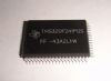
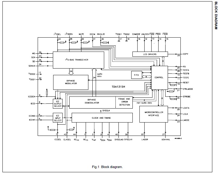
The Digital Audio Input/Output circuit (DAIO) of the TDA1315H is a complete transceiver for biphase-mark encoded digital audio signals that conform to the SPDIF and “IEC 958” interface standards (consumer mode), made in the full CMOS-process C200. In the receive mode, the TDA1315H adjusts automatically to one of the three standardized sample frequencies (32, 44.1 or 48 kHz), decodes the input signal and separates audio and control data. A clock signal of either 256 or 384 times the sample frequency is generated to serve as a master clock signal in digital audio systems. In the transmit mode, the TDA1315H multiplexes the audio control and user data and encodes it for subsequent transmission via a cable or optical link.
Parametrics
TDA1315H absolute maximum ratings: (1)VDD, supply voltage (pins 3, 17 and 42): -0.5 to +6.5 V; (2)IDD, supply current per pin (pins 3, 17 and 42): - 50 mA max; (3)Vall, voltage supplied to all pins without current limitations: -0.5 to VDD + 0.5 V; (4)II/O, input/output current on any pin except supply pins and pins 8, 12 to 16, 29 and 40: ±10 mA max; (5)II, input current pins 12 to 16 and 29 at VO > VDD + 0.5 V; output disabled: ±10 mA max; (6)II/O, input/output current pins 12 to 16 and 29 at VO < VDD + 0.5 V: ±20 mA max; (7)I8, input/output current pin 8: ±60 mA max; (8)I40, input/output current pin 40: ±80 mA max; (9)Ptot, total power dissipation: 500 mW max; (10)Tstg, storage temperature: -65 to +150 ℃; (11)Tamb, operating ambient temperature: -20 to +70 ℃; (12)Ves, electrostatic handling: -2000 to +2000 V.
Features
TDA1315H features: (1)Transceiver for SPDIF and “IEC 958” encoded signals; (2)High sensitivity input for transformer-coupled links; (3)TTL-level input for optical links; (4)Built-in IEC input selector; (5)Built-in IEC feed-through function; (6)Automatic sample frequency (fs) detection; (7)System clock recovery from IEC input signal; (8)Low system clock drift when IEC input signal is removed; (9)Error detection and concealment; (10)PLL lock detection in transmit mode; (11)Serial audio interface conforms to I2S-bus format; (12)Auxiliary I2S-bus input for Analog-to-Digital Converter(ADC); (13)Audio output selector; (14)Microcontroller-controlled and stand-alone mode; (15)128-byte buffer for user data; (16)Bytewise exchange of user data with microcontroller; (17)Decoding of Compact Disc (CD) subcode Q-channel data; (18)Support for serial copy management system (SCMS); (19)Light Emitting Diode (LED) drive capability (sample frequency and error indication); (20)Pin-selectable device address for microcontroller interface; (21)Power-down mode.
Diagrams
| Image | Part No | Mfg | Description |  |
Pricing (USD) |
Quantity | ||||||||||||
|---|---|---|---|---|---|---|---|---|---|---|---|---|---|---|---|---|---|---|
 |
 TDA1315H |
Other |
|
Data Sheet |
Negotiable |
|
||||||||||||
| Image | Part No | Mfg | Description | |
Pricing (USD) |
Quantity | ||||||||||||
|
TDA1001B |
Other |
|
Data Sheet |
Negotiable |
|
||||||||||||
|
TDA1001BT |
Other |
|
Data Sheet |
Negotiable |
|
||||||||||||
|
TDA10021HT |
Other |
|
Data Sheet |
Negotiable |
|
||||||||||||
|
TDA10025HN/C1,518 |
NXP Semiconductors |
Modulator / Demodulator Dual Cable (QAM) Demodulator |
Data Sheet |
|
|
||||||||||||
|
TDA10025HN/C1,551 |
NXP Semiconductors |
Modulator / Demodulator DUAL CBL DEMODULATOR |
Data Sheet |
|
|
||||||||||||
|
TDA10025HN/C1,557 |
NXP Semiconductors |
Modulator / Demodulator DUAL CBL DEMODULATOR |
Data Sheet |
|
|
||||||||||||